We often find that some people are confused by wheel sizes when it comes to buying replacements. In this post I will explain what these measurements mean, and what to look out for when buying new wheels.
Trailer wheels are very similar, if not the same in some cases as car wheels. There are a lot of different wheels available, and as a trailer owner it would be useful to have some knowledge of them.
Wheel size
First of all you will need to know where everything is located and how to take some basic measurements of your wheels. The diagram below shows the basic layout of a wheel rim.

The diagram below shows how you would measure the nominal diameter and inside width of the rim. This distance is most commonly measured in inches.

As you can see form the diagram above, the rim width is measured on the inside of the wheel. If the markings on the rim are still readable the width in inches will be followed by a letter J, then the diameter.
For example 4.5J13 means the inside width of the rim is 4.5″ and the Diameter is 13″.
There can be several pieces of information marked on a wheel rim. This could include:
- The wheel manufacture. This should be marked on all wheels.
- Bead type. This normally follows the wheel size.
- Part number to get a direct replacement. Part numbers can sometimes be cross referenced in order to find similar wheels.
Other information that can be found may include:
- Rim offsets.
- Country of manufacture.
- Date or date code.
- Occasionally the manufacturer will give the PCD of the mounting holes.
The 3 most important measurements when looking for new wheels are the rim size, the PCD and the offset.
If you can get these measurements correct the wheel will fit.
Bead type

Beads are not really needed on smaller rims, therefore most small rims are manufactured without them. If your rim does have beads, the markings for each bead type and a description of each can be found below.
H – denotes one rounded bead on the outside of the rim.
H2 – denotes two rounded beads. The same as the image above.
FH – denotes a flat hump on the outside of the wheel
CH – denotes a combination of humps. One flat on the outside, and one rounded on the inside.
SL – these markings are used on wide wheels and mean ‘Special ledge’.
Generally in trailer wheels you will see a H, H2 or no bead at all.
Related posts:
Working out your PCD.
Trailer wheel offset.
Tyre speed ratings.
Tyre load index.
If you are looking to buy trailer wheels and tyres, choose from a large selection at 
Known problems with LED trailer lights on later cars.
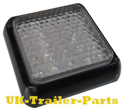
LED Lights are getting a lot more popular on trailers for the following reasons:-
- They save energy meaning that you use very slightly less fuel.
- There is no filament in an LED they last a lot longer than a bulb.
- They do not stick out as much as a bulb light meaning they do not get broken as easily.
- They are popular with plant and recovery companies as some will work on 12 and 24V systems meaning that bulbs do not need changing when changing tow vehicle from lorry to van or 4×4.
- LED lights are far brighter and look much better than most bulb lights
We do find compatibility problems with LED trailer lights and high-end vehicles since 2000 fitted with ‘plug-in’ wiring kits.
Vehicles fitted with aftermarket towbars usually are not fitted with these plug-in systems. Towbar fitters are usually trying to do the job as cheap as possible and use a bypass system instead as this is a lot cheaper. With all bypass relays fitted on cars the lights work as they should but LED lights do not draw enough power for the indicator buzzer to work on most of these relays.
There are 2 problems that plug-in systems can give. Some systems send test pulses to check that the vehicle lights are functional, this is what causes LED lights to flash. Other systems are not activated until a load is detected. The problem here is LED’s are so sensitive they don’t have sufficient load to trigger the sensors on the plug-in system. Therefore they are not detected, and as a result no lights work.
The vehicles that we have seen the problems on are as follows.
Mercedes. Most models from 2000 both problems dependant on the kit fitted.
BMW. Flashing LED lights on most models but some can be cured by introducing a load, others need bypassing.
Discovery 3. Flashing on indicators only.
Range Rover and Range Rover Sport. Flashing indicators only.
Iveco Trucks. All lights flashing.
We have had various other reports but we have only experienced the list above for ourselves.
Towing and Trailers Ltd will plug an LED Lightboard into your car at their premises to test your vehicle free of charge before you buy LED lights.
If you are looking to buy trailer lights, choose from a large selection at 
Back to Top |
Comments Off on Problems with LED trailer lights on later cars
First of all what does PCD mean?
PCD stands for Pitch Circle Diameter. This is the diameter of a circle that is used to measure the spacing between the wheel studs on a hub or the stud holes in a wheel rim. In this guide are diagrams showing the most popular PCD’s and stud sizes used. These will help you measure your PCD before purchasing new hubs or wheels.
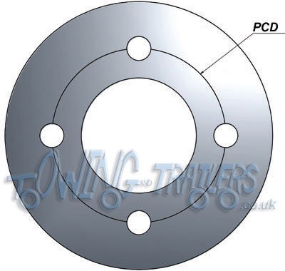
As shown on the diagram above it is easy to find the PCD on a 4 stud wheel. Just measure from the centre of one stud to the centre the opposite stud. This will work for any even number of studs.
Please note there are two PCD’s that are very similar. These are 4″ (101.6mm) and 100mm. As these are so close some people get this measurement wrong as they mistake 4″ for 100mm if they are used to using imperial measurements. The same goes for 100mm being mistaken for 4″ if people are used to metric measurements.
For other stud patterns i.e. 3 or 5 stud, the above method will not work. There is another way that will work on any stud pattern including those with an even amount of studs. The two measurements shown on the diagram below labeled as A and B are needed:
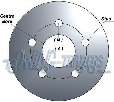
Dimension A is the diameter of the centre bore (hole in the middle of the wheel).
Dimension B is the distance from the edge of the centre bore to the centre of any stud.
To work out the PCD is easy. Simply add A + B + B. See example below:
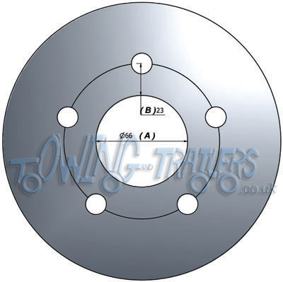
To work the PCD shown above it is just 66 + 23 + 23 = 112mm
Below are a some of the most popular PCD’s used on trailer wheels.
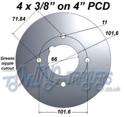
This is probably the most common PCD used on small trailers. It has a 3/8″ stud. Due to the size of the studs it is limited to wheel size and weight capacity. This is not advised to be used on wheels larger than 10″ and weights above 750kg per axle. This is also the PCD used on old mini wheels. There has been a heavy duty 4″ PCD used in the past that gave extra carrying capacity and allowed larger wheels to be used. It had a 7/16″ (11.1mm) stud and was used on some Indespension wheels amongst others. This has been superseded by the 4 stud 100mm PCD shown below.
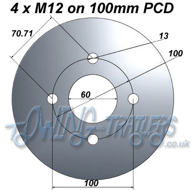
4 x 100mm can be used on smaller trailers that require larger wheels. The carrying capacity is higher as the studs are larger (12mm) and this gives a stronger fixing point. This PCD is often used on caravans.
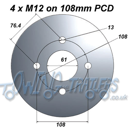
4 x 108mm is usually used on Ford car wheels (please check your wheel measurements). The carrying capacity is higher as the studs are larger (12mm) and this gives a stronger fixing point.

4 x 5.5″ is a commonly used PCD, and it comes with either a 12mm or ½” (12.7mm) stud. This is a heavy duty 4 stud pattern, although we do not recommend using on weights above 1300kg per axle. We tend to use this on all braked suspension up to 1300kg per axle. A lot of trailer manufactures use this on their suspension units.
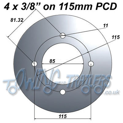
4 x 115mm is mainly used on European and flat-pack trailers such as Erde, Daxara and Franc. Other small general purpose trailers such as the Maypole MP711 also use this pattern.

4 x 130mm PCD is used by French manufacturers of trailers, 115mm PCD is used on smaller 8 or 10″ wheels and 130mm PCD is used on the bigger 13″ wheels that carry more weight.
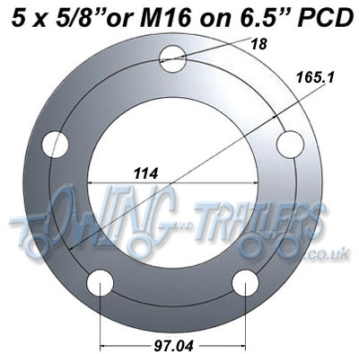
5 x 6.5″ (165.1mm) is a very popular PCD as it will accommodate any trailer weight. It uses a larger diameter stud such as a 16mm or 5/8inch (15.875mm). It is commonly used by Ifor Williams trailers among other manufacturers. We try and use it on all wheels and suspension rated for 1500kg and above.
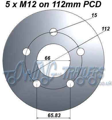
5 x 112mm is used on small wheels for building low loading trailers. These are often used by Brian James and Bateson trailers, mainly on large flat bed or beavertail car transporters where the bed needs to be low. This pattern uses a 12mm stud and we would not recommend using on axle weights over 1500kg.

5 x 140mm PCD was another common stud pattern. It was mainly used on Indespension axles. However wheel rims are no longer manufactured on this stud pattern making it now obsolete.
Related posts:
Wheel Measurements
Trailer Wheel Offset
Trailer Tyre Load Index
Tyre Speed Ratings
If you are looking to buy trailer wheels and tyres, choose from a large selection at 
Back to Top |
Comments Off on Working out Pitch Circle Diameters (PCD)
The 7 pin N type plug and socket is still the most common connector for towing. This supplies power to the road lighting of your trailer or caravan. This has now been replaced by 13 pin Euro plugs on all new caravans.
Below is a diagram for the original plug and socket showing the functions of each pin.
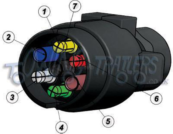
| Pin No. |
Colour |
Function |
| 1 |
Yellow |
Left Indicator |
| 2 |
Blue |
Fog Light |
| 3 |
White |
Earth |
| 4 |
Green |
Right Indicator |
| 5 |
Brown |
Right tail / Side light |
| 6 |
Red |
Brake / Stop lights |
| 7 |
Black |
Left tail / Side light |
Here are two wiring diagrams for the 7 pin ‘N’ type trailer electrical plug.
The first diagram is a simple set up of two brake lights, two indicators and two side lights. Click on the image below to enlarge it.

The second diagram shows two brake lights, two indicators, two side lights and a fog light. Click on the image below to enlarge it.

Other wiring diagrams on this site are listed below:
7 pin ‘S’ type plug and socket wiring diagram.
13 pin Euro plug wiring diagram.
7 way universal bypass relay wiring diagram.
Split charge relay wiring diagram.
To purchase components for trailer wiring please visit – www.towingandtrailers.com
Back to Top |
Comments Off on 7 pin ‘N’ type trailer plug wiring diagram
TEC2M Auto Switch Combi Relay
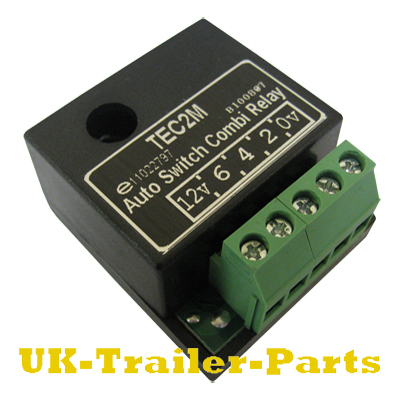
This relay automatically senses the condition of the towing vehicles alternator and diverts some of the current charging it’s battery to the caravan’s battery or fridge as well. This happens automatically when sensors trigger a split charge relay at a set voltage. This does not require a separate lead from the ignition switch as the switch in the relay is automatic.
It is important to use cables with sufficient stranding to prevent voltage drop as this can stop the relay from functioning. Cable that has a minimum stranding of 35/0.3 (2.5 sq mm) should be suitable for the 12v feed from the battery to the relay. Cable with a minimum stranding of 16/0.2 (0.5 sq mm) should be enough for the earth.
This relay has been designed to handle loads of up to 15 amps.
Below is a wiring diagram for the TEC2M, please click to enlarge it.

To purchase trailer parts and towing accessories please visit towingandtrailers.co.uk

Back to Top |
Comments Off on TEC2M Auto Switch Combi Relay wiring diagram
Cable cover plates form a protective cover for the exposed area of brake cable that connects to the expander in the brake. The cable cover is made up of two plates that slot together and are held in place by the brake cable itself. The first of these two plates is permanently fixed to the back plate of the trailers brakes.
Cable cover plates on trailer brakes are a common area for maintenance as they are usually the first to show signs of corrosion. This is because the underside of your trailer is far more likely to suffer the effects of corrosion due to the water and salt picked up from the road.
The example below shows a poorly maintained back plate from a brake unit. You can see that the back plate is badly corroded, and the fixed half of the cable cover plate has snapped.

If you are sure that the corrosion to the brake unit is only superficial and there is no severe damage, it is possible to clean it up with a wire brush and replace the damaged cable cover plate.
As you can see in the picture below, the hub and brake assembly have to be removed in order to perform these repairs.

In order to take off the old cover plate you must remove the weld fixing it to the back plate using a grinder. Take care not to damage any other part of the brake while doing this.

After removing the weld, the old cover plate should not be too hard to separate from the brake back plate.

Use a hand file to clean up the area you have just been grinding.

Slot both parts of the new cable cover together and position them in the back plate. Next you will have to weld the top cover plate in place.

Remember that only the top cover plate needs welding to the brake back plate. The bottom cover plate is held in place by the brake cable and can be quickly released to allow access to the expander.

The weld only needs to be about an inch in length, just enough to hold the cover plate in place.

In the example below you can see the top half of the new cover plate firmly fixed to the brake back plate.

Providing that the expander inside the brake is in working order, you can use a wire brush to clean up the rest of the brake and re-assemble it. Connect the end of the cable to the expander, re-fit the bottom cable cover plate, and slide the metal ‘cup’ of the cable over the ends of both cover plates to hold them together.

Related articles:
Identifying trailer brake cables
Brake cable replacement / fitting guide
Replacing trailer brake shoes
If you are looking to buy trailer brake parts, choose from a large selection at… 
Back to Top |
Comments Off on Replacing trailer brake cable cover plates
Here is a guide to fitting / replacing a triple lock head on a braked coupling.
First of all you will have to remove your old coupling head.
If you have a standard coupling head you should be able to remove it by undoing the two bolts that fasten it to the drawbar. If you are replacing a triple lock head, things are going to get a little trickier.
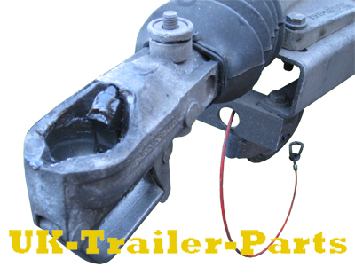
Triple lock heads have a small security device that seals one of the bolts securing it to the drawbar. You can only remove this is by cutting through it with a grinder, exposing the bolt on the inside.
The example below shows where to cut through.

You must also turn the head over and cut through the device securing the nut.
Cut the tie wraps from around the rubber bellows and slide them out of the way. Now the bolts have been exposed you can remove them with a ratchet or power tool. Remember though, you will need to use thin walled sockets to fit into the ground off security devices. Spanners and impact sockets will not fit.

Remove the old head from the drawbar.

Slide the new head onto the drawbar and line up the holes where the bolts go. Begin to fit the bolts that secure the head to the drawbar, remembering to fit the new devices that will later seal the bolts.
You will notice that the hole on the side of the head is obscured by something inside the drawbar. This is a damper that connects to the back of the head. It must be levered into position so that a bolt can pass through the eye on the end of it.
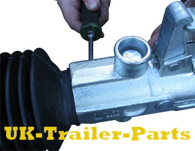
Lever the damper with a screwdriver until you can see that the eye of the damper and the holes in the head line up. When they line up, push the bolt through them. This is a little tricky as you will have to hold the damper in place with one hand, while inserting the bolt with the other.

When both bolts are in place tighten them up. Remember that you will need thin walled sockets to fit inside the security device.

Now you can seal the security devices by hammering these small metal disks into them.

The metal disks have tapered edges to make them easier to hammer in.
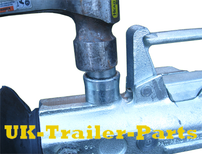
The metal seal for the device protecting the nut has a hole in the centre of it, this allows it to fit over the end of the bolt. To hammer this into place you will need to use a large socket so that you can hammer the metal disk without hitting the bolt. See the example below.

Turn the head back so it is facing the correct way up and re-fit the rubber bellows. Stretch the bellows back over the coupling head so that it covers the unprotected bolt. Use tie wraps at each end to keep it in place and make a good seal that will keep water out.

If you are looking to buy trailer parts, choose from a large selection at… 
Back to Top |
Comments Off on Triple lock head fitting/replacment guide (Braked coupling)
Many modern cars have Multiplexed or Can bus wiring systems. Wiring systems such as Can bus were developed in order to be a simpler and more cost effective alternative to the traditional wiring harness.
This advancement in wiring has also led to the development of various fault finding and diagnostic systems. One fault finding system sends small test pulses to all of the lights in the system to identify faulty bulbs. If a faulty bulb is detected the diagnostic system will display a symbol on the dashboard, alerting you to the fault.
This system can cause problems when trying to fit a tow bar, LED lights, or even when towing a trailer that has been fitted with LED trailer lights. Unlike regular bulbs, LED lights are so sensitive they will pick up the small test pulses through Can bus and flash constantly. As well as constant flashing, LED lights do not have sufficient ‘Load’ enough to trigger the diagnostic system and dashboard warning symbol.
This can be avoided by fitting an expensive manufacturer approved plug-in wiring kit when your tow bar is installed. This should resolve any problems with the diagnostic or fault finding systems, but it won’t be cheap.
Fitting this Universal Bypass Relay to your car between the wiring system and trailer plug socket bypasses all of the fault finding and diagnostic systems created by Can bus. This basically leaves you with a standard 12v power supply. This allows LED lights to function properly, without flashing, at a the fraction of the cost of a dedicated plug-in kit.
This relay isolates the 12v power supply and bypasses any fault finding or diagnostic systems after the relay. A fuse should be fitted to the relay’s power supply so in the event of a fault or short circuit your car remains unaffected. Please be aware that no system on your car will alert you to faults with your trailer’s lights while using this relay.
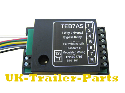
On the left hand side of the relay are 8 colored cables, a 12v power terminal, and another terminal marked TT. The 12v power terminal requires a dedicated feed (with fuse) directly from the cars battery, while the terminal marked TT is for an optional ‘tell tale’ dashboard light.
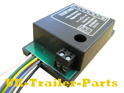
The 8 colored cables have the following functions:
Yellow – Left Indicator
Blue – Fog Light
White- Earth
Green – Right Indicator
Brown – Right Tail / Side Light
Red – Brake / Stop Lights
Black – Left Tail / Side Light
Gray – Reverse Light
On the right hand side are 7 terminals marked 1, 2, 4, 5, 6, 7 and ‘R’. There is no terminal 3 as this is an earth wire which must be secured to the vehicles bodywork.

These correspond to the pins in the trailer plug socket and are wired as shown below.
Click the image to enlarge it.

To purchase trailer parts and accessories, including tow bar wiring components, please visit towingandtrailers.co.uk :

Back to Top |
Comments Off on 7 Way universal bypass relay wiring diagram


